The idea behind this project was essentially that we had an implantable medical device, designed to be affixed to bone that we needed to test. An axial force needed to be applied to the device in a consistent manner, in a way that we could easily measure the force applied and come up with conclusions from our data and observations.


After a couple whiteboard brainstorming sessions with my supervisor, I had a clear sense of direction for this fixture and a good idea for the constraints and design requirements of this project.
I then took to Solidworks to begin designing the fixture.

After some time, I had a complete design and got approval from my supervisor to begin ordering parts online and fabricating custom parts for it.
The first thing I did was check our stock of 80/20 rails to see if we had the correct sizes I needed. We had the right rails but I had to cut them to the correct length. I ordered the corner gussets, pneumatic cylinder, swagelok fittings, and any necessary hardware from McMaster-Carr and began fabricating the custom parts.
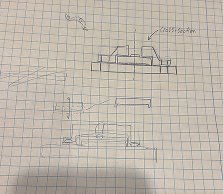
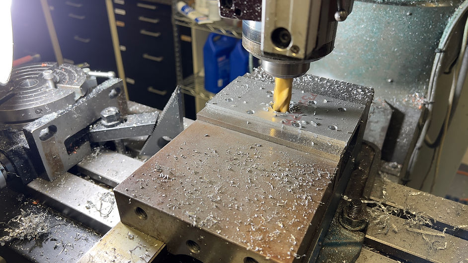
I made some hand sketches of the custom brackets to take with me to the machine shop and printed out 1:1 templates to indicate where holes needed to be drilled. In the shop we had a modified Bridgeport vertical CNC machine, so instead of uploading a CAM file to the machine, I had to calibrate against the edges of the aluminum slabs manually, input that information into the Bridgeport computer, and enter in the x and y coordinates for each cut. That is why having a cartesian layout of the holes was useful for me.

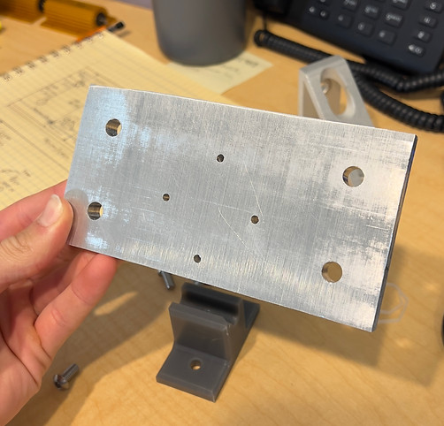
After the machining process was done, I had two beautiful custom brackets for this fixture. I clamped one of them down in a vice and used an orbital sander to remove any small chips and imperfections from the surface. I forgot to do it on the other one so the finish is bad on the left bracket :( . The result of this whole process is shown below.

After the brackets were made, I attached them to their respective parts. The bracket on the right was attached to a huge pneumatic cylinder and eventually to some corner gussets connecting it to the frame. The bracket on the left Was also attached to the frame with some corner gussets, and I attached a custom designed load cell clamp to it, with the center being the point of contact we would push the device against. I made sure the clamp didn't apply any pressure to the measuring point when screwed into the bracket.


After that was done I secured everything to the fixture frame.


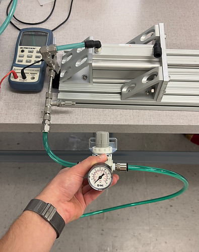
Lastly, I attached the pneumatic tube fittet together with a pressure regulator, and some swagelok fittings. Having the swagelok fittings ensured a really tight seal which was good because we were working with pretty high pressures and wanted to take steady measurements over time.
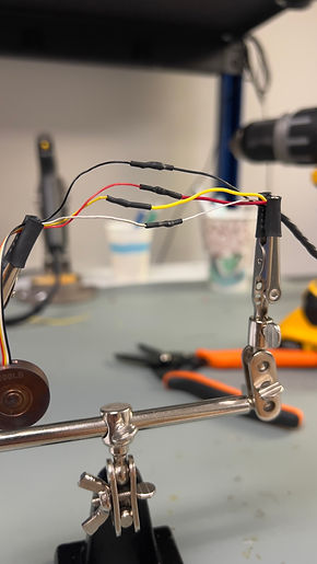
Before attaching the load cell to the bracket I made up above, I played around with it and tested it in the video below.

Some images showing the process of soldering longer wire connections to the load cell, as well as how it fits into the clamp I designed for it.